The Thermospray Interface
The thermospray interface
evolved from the
simple direct inlet system, by the rather simple modification of
heating the tip of the entry tube. When the tip is heated, the
solvent is vaporized right at the tip, and not somewhere inside the
delivery tube. This results in much better control of both the
nebulizing process and the ionizing process. One of the first reports
of the successful use of the thermospray was by Covey and Henion
[12]. Subsequently a number of different forms of the device were
described, but the relatively simple form of the thermospray
interface described by De Wit et al. [13] in 1987,
will be
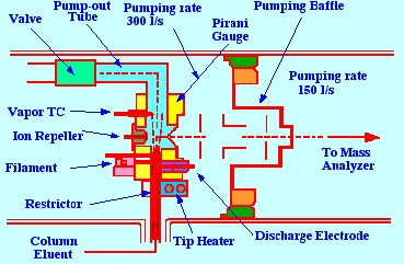
used as an example to describe the operating principle. A diagram of
the thermospray interface, devised by De Wit et
al.
is shown in figure 19. The device consists of a stainless steel tube,
terminating in a metal cap made from a high-conductivity metal such
as copper. Through the center of the stainless steel tube and copper
cap passes a conduit carrying the reagent gas. In the center of the
reagent conduit passes a section of a fused silica open tubular
column (which carries the solution of the sample) and which projects
slightly beyond the reagent conduit, into the ion source of the mass
spectrometer. The sample tube first passes through a T union, to
allow the reagent gas to be introduced into the annular space between
the inner tube and the conduit, and then into the thermospray probe
itself. A cartridge heater is placed in the copper cap together with
a thermocouple, which measures the temperature of the probe tip, and
provides a controlling signal to maintain the tip at a selected
temperature.
In a similar manner to the
direct inlet
system, the flow of sample solution had to be restricted, because the
pumping rate of the mass spectrometer vacuum system was limited. The
properties of the thermospray system were examined by Voyksner et
al. [14]. They noted that the thermal spray system frequently
produced molecular weight information (parent ions), and exhibited
lower detection limits than the other sampling techniques. They also
noted that using a thermal spray system with a 0.1 M ammonia acetate
buffer, and a solvent that contained a high proportion of water, very
high sensitivities could be achieved. The optimum interface
temperature varied with solvent composition and could be determined
by maximizing the solvent buffer ion intensities.
The spectra obtained from
thermospray
ionization resemble Chemical Ionization using ammonia as the chemical
ionization reagent. The system produces protenation, ammonium
addition and proton-bound solvent molecular clusters. The ionization
procedure with this system was reported to be very soft and very few
molecular fragment ions were formed. The system was successfully used
for the analysis of triazine herbicides and organo-phosphorus
pesticides.
Blakely and Vestal [15] employed
the
thermospray sample inlet system with the quadrupole mass
spectrometer, and demonstrated that it could cope with sample flow
rates up to 2 ml/min,
with
an aqueous mobile phase. Weakly ionized mobile phases require a
conventional electron beam to be used to provide gas-phase reagent
ions for the Chemical Ionization of the solute.
A more recent form of
thermospray liquid
sampling system, the Vestec Model 201 used by Via and Taylor [16] is
shown in figure 20. This interface can handle flow rates of up to 1.5
ml/min,
and incorporates
two oil diffusion pumps backed by a single mechanical pump. The two
pumps differentially exhaust the vacuum manifold, the source, and the
analyzer regions of a Quadrupole Mass Spectrometer. A further two
diffusion pumps, backed by a single mechanical pump, are coupled
directly to the source, opposite the sample inlet. This pump removes
about 99% of the vaporized solvent, whereas the heavier molecules
pass through an ion aperture in the sampling cone, and into the mass
spectrometer. The sample solution passes to the spray orifice,
through a fused silica tube, which is joined by a 1/16 in. union to a
length of stainless steel tubing, in the manner shown in figure 21.
The ions are formed immediately
after the
nebulization, and pass alongside a repeller plate, held at a high
potential, that impels the ions through a hole into the ion source.
Once in the ion source, the ion optical system of the mass
spectrometer directs them into the analyzer section of the
spectrometer. The reagent gas is methane and its flow is controlled
by separate needle valves.
A common problem in the
explosives industry
is the identification of stabilizer derivatives in the explosive
itself, the presence of which will indicate its age or stability.
Many nitrocellulose propellants are stabilized with diphenylamine .
This stabilizer is thought to react with any NO2 that
is
released during aging or decomposition, to produce nitrated
derivatives of the stabilizer. Consequently, an analytical method
that will identify and measure the presence of nitro-diphenylamines
in an explosive is highly desirable. Via and Taylor developed a
chromatographic method to separate, identify and assay the amount of
nitrated diphenylamines present in a nitrocellulose explosive sample.
The results from a test sample, containing the stabilizer and its
derivatives, that was separated by SFC and analyzed by the mass
spectrometer are shown in figure 22.
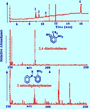
-
2,6-dinitrotoluene,
2. impurity, 3. 2-nitrodiphenylamine, 4. 4-nitrodiphenylamine.
The
reconstructed total ion current chromatogram of the separation is
shown at the top of figure 22. It is seen that a good separation of
the solutes of interest was obtained. It is also seen that the
spectra for 2,4 dinitrotoluene and 2-nitrodiphenylamine are clear and
unambiguous and would allow the substance to be identified with
certainty. The authors claimed that the sensitivity of the analytical
procedure was about 1 ng. However, according to Via and Taylor, in a
private communication, Wilkes of the Vestec Corp. claimed that
satisfactory spectra could be obtained from samples present at the
picogram level. For example, 60 pg of 2-nitrodiphenylamine injected
on the column could provide an identifiable mass Spectrum.
About the Author
RAYMOND PETER WILLIAM SCOTT was born on June 20 1924 in Erith, Kent, UK. He studied at the
University of London, obtaining his B.Sc. degree in 1946 and his D.Sc. degree in 1960.
After spending more than a decade at Benzole Producers, Ltd. Where he became head of
the Physical Chemistry Laboratory, he moved to Unilever Research Laboratories as
Manager of their Physical Chemistry department. In 1969 he became Director of Physical
Chemistry at Hoffmann-La Roche, Nutley, NJ, U.S.A. and subsequently accepted the position
of Director of the Applied Research Department at the Perkin-Elmer Corporation, Norwalk, CT, U.S.A.
In 1986 he became an independent consultant and was appointed Visiting Professor at Georgetown
University, Washington, DC, U.S.A. and at Berkbeck College of the University of London; in 1986
he retired but continues to write technical books dealing with various aspects of physical chemistry
and physical chemical techniques. Dr. Scott has authored or co-authored over 200 peer reviewed
scientific papers and authored, co-authored or edited over thirty books on various aspects of
physical and analytical chemistry. Dr. Scott was a founding member of the British chromatography
Society and received the American Chemical society Award in chromatography (1977), the
M. S. Tswett chromatography Medal (1978), the Tswett chromatography Medal U.S.S.R., (1979),
the A. J. P. Martin chromatography Award (1982) and the Royal Society of Chemistry Award in
Analysis and Instrumentation (1988).
Dr. Scott’s activities in gas chromatography started at the inception of the technique,
inventing the Heat of Combustion Detector (the precursor of the Flame Ionization Detector),
pioneered work on high sensitivity detectors, high efficiency columns and presented fundamental
treatments of the relationship between the theory and practice of the technique.
He established the viability of the moving bed continuous preparative gas chromatography,
examined both theoretically and experimentally those factors that controlled dispersion
in packed beds and helped establish the gas chromatograph as a process monitoring instrument.
Dr. Scott took and active part in the renaissance of liquid chromatography,
was involved in the development of high performance liquid chromatography and invented
the wire transport detector. He invented the liquid chromatography mass spectrometry
transport interface, introduced micro-bore liquid chromatography columns and used them
to provide columns of 750,000 theoretical plates and liquid chromatography separations
in less than a second.
Dr. Scott has always been a “hands-on” scientist with a remarkable record of accomplishments in chromatography ranging from hardware design to the development of fundamental theory. He has never shied away from questioning “conventional wisdom” and his original approach to problems has often produced significant breakthroughs.