ANALYTICAL SPECTROSCOPY
by Raymond P. W. Scott
D.Sc., F.R.S.C., C.Chem., C.Sci. F.A.I.C, F.C.S.
Essential Information for the Analytical Chemist
Specialising in custom-designed, precision scientific instruments, built, programmed and calibrated
to the most exacting standards. The range includes precision dataloging barographs,
with built-in statistical analysis, Barographic Transient Event Recorders
and computer-interfaced detectors and sensors
for environmental monitoring & process control.
A site dedicated to scientific techniques, experimental methods, &
investigative tools for the inventor, researcher
and laboratory pioneer. Articles on glassblowing, electronics, metalcasting, magnetic
measurements with new material added continually. Check it out!
www.drkfs.net
The atomic emission
spectrometer is versatile, highly sensitive and very selective. The
procedure is to aspirate the sample, which will be a solution of the
element (usually an aqueous solution) into the high temperature
volume of the emission system and then monitor the light emitted with
a suitable optical system that usually terminates in a Diode Array
sensor. The nebulizer is normally a very simple device a diagram of
which is shown in figure 2.
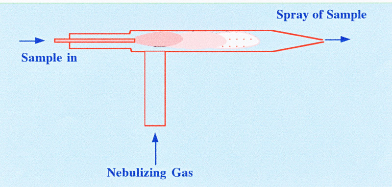
The sample, often in an aqueous
solution, is pumped by means of a peristaltic pump through a jet into
a concentric tubular cavity through which a suitable gas is flowing
at relative high velocity. The system tends to act as a miniature
‘spray drier’ the liquid breaking up into fine droplets
that evaporate and leave the solid sample as minute particles
entrained in the moving gas. The evaporation process, however, is not
completely efficient and water is carried forward with the particles
and must be removed. Another type of nebulizer is the ‘cross-flow
nebulizer’ a diagram of which is shown in figure 3.
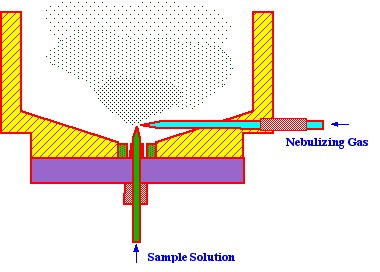
The advantage claimed for this type
of nebulizer is more efficient spray production due to the sample
liquid being fed in, normal and close to the nebulizing gas stream.
However, this is also not one hundred percent efficient and a device
still has to be incorporated into the sampling system that removes
excess, liquid sample. The device used for this purpose is also very
simple and is called the spray ‘chamber’. A diagram of a
spray chamber is shown in figure 4.
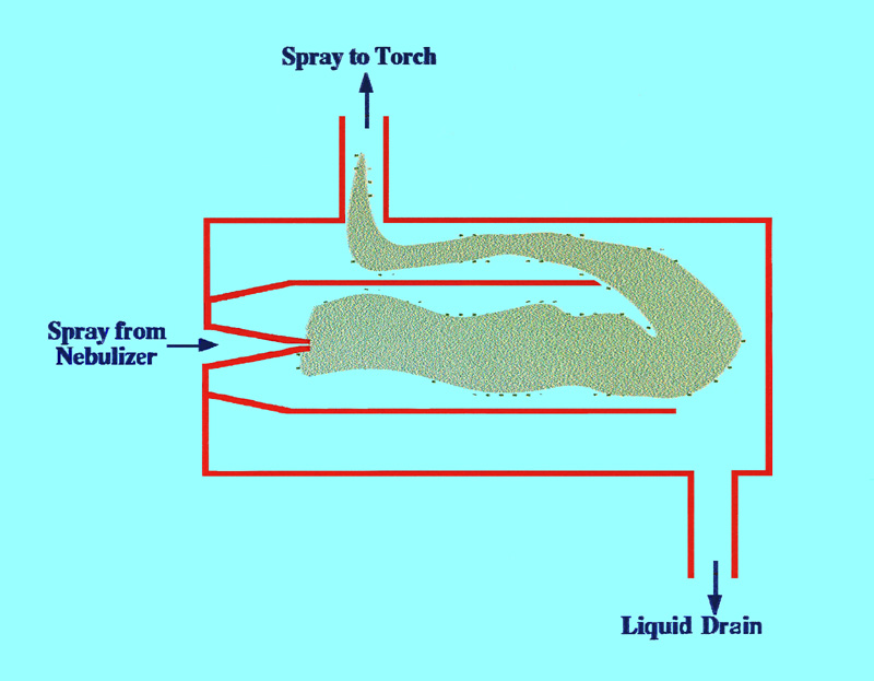
It is seen that the spray chamber
consists of two concentric tubes sealed at either end. The outer tube
has an exit at the top that allows the gas containing the particles
to pass to the ‘torch’. At the bottom of the tube there
is a ‘drain’ exit where the liquid caught on the walls of
the inner and outer tubes collect and pass to waste. The gas carrying
the sample particles then passes into the torch where the sample
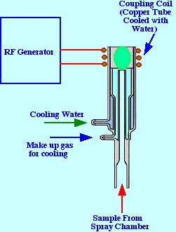
atoms are heated to a very high temperature A diagram of a ‘torch’
is shown in figure 5. The torch consists of three concentric tubes
made of quartz or some other appropriate material. A copper coil,
though which water circulates for cooling purposes, surrounds the top
portion of the torch and is connected to a radio frequency source.
The plasma gas, e.g. argon, is used as the nebulizing gas and
a second flow of argon enters the torch at the base to act both as a
coolant and as part of the plasma forming agent. In many torches the
base of the torch is also cooled by a water jacket. A spark produced
by a Tesla coil initiates the plasma formation by generating some
electrons. The RF power (0.2 to 2.0 kW and 27 to 40 Mhz)) produces
electric and magnetic fields that accelerates the electrons by
inductive coupling (inductively coupled plasma ICP) The resulting
high energy electrons cause further argon ionization by collision
which continues as a chain reaction producing the plasma. The
temperature of the plasma ranges from 6000 C to 10,000 C and appears
as an intense brilliant white ‘tear-drop’ shaped
fireball.
The
distribution of the different zones in the plasma is depicted in
figure 6. The lower part of the plasma is the induction zone
where the effect of the RF radiation starts to become affective.
Above this is the initial radiation zone where the plasma
temperature may reach as high as 10,000 C. Above the initial zone is
a larger plasma volume that is called the analytical zone and
it is the light from this area that is used for analytical purposes.
The analytical zone changes into a plasma tail before it
eventually becomes extinguished. The nebulizer spray chamber, torch
and other essential parts of the instrument are connected together if
the manner shown in figure 7.
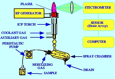
Figure 7
shows a general layout of ICP the atomic Emission Spectrometer
system. Individual instruments may differ in detail but the layout
given in figure 7 will be a reliable guideline for most atomic
Emission Spectrometers
About the Author
RAYMOND PETER WILLIAM SCOTT was born on June 20 1924 in Erith, Kent, UK. He studied at the
University of London, obtaining his B.Sc. degree in 1946 and his D.Sc. degree in 1960.
After spending more than a decade at Benzole Producers, Ltd. Where he became head of
the Physical Chemistry Laboratory, he moved to Unilever Research Laboratories as
Manager of their Physical Chemistry department. In 1969 he became Director of Physical
Chemistry at Hoffmann-La Roche, Nutley, NJ, U.S.A. and subsequently accepted the position
of Director of the Applied Research Department at the Perkin-Elmer Corporation, Norwalk, CT, U.S.A.
In 1986 he became an independent consultant and was appointed Visiting Professor at Georgetown
University, Washington, DC, U.S.A. and at Berkbeck College of the University of London; in 1986
he retired but continues to write technical books dealing with various aspects of physical chemistry
and physical chemical techniques. Dr. Scott has authored or co-authored over 200 peer reviewed
scientific papers and authored, co-authored or edited over thirty books on various aspects of
physical and analytical chemistry. Dr. Scott was a founding member of the British chromatography
Society and received the American Chemical society Award in chromatography (1977), the
M. S. Tswett chromatography Medal (1978), the Tswett chromatography Medal U.S.S.R., (1979),
the A. J. P. Martin chromatography Award (1982) and the Royal Society of Chemistry Award in
Analysis and Instrumentation (1988).
Dr. Scott’s activities in gas chromatography started at the inception of the technique,
inventing the Heat of Combustion Detector (the precursor of the Flame Ionization Detector),
pioneered work on high sensitivity detectors, high efficiency columns and presented fundamental
treatments of the relationship between the theory and practice of the technique.
He established the viability of the moving bed continuous preparative gas chromatography,
examined both theoretically and experimentally those factors that controlled dispersion
in packed beds and helped establish the gas chromatograph as a process monitoring instrument.
Dr. Scott took and active part in the renaissance of liquid chromatography,
was involved in the development of high performance liquid chromatography and invented
the wire transport detector. He invented the liquid chromatography mass spectrometry
transport interface, introduced micro-bore liquid chromatography columns and used them
to provide columns of 750,000 theoretical plates and liquid chromatography separations
in less than a second.
Dr. Scott has always been a “hands-on” scientist with a remarkable record of accomplishments in chromatography ranging from hardware design to the development of fundamental theory. He has never shied away from questioning “conventional wisdom” and his original approach to problems has often produced significant breakthroughs.